Wednesday, 29 February 2012

WEEK 7

Comparison Study of audio amplifier performances using Class AB, B and D topologies in portable audio devices.

In this week, I'm construct the circuit and simulation of Class B audio amplifier using Multisim. For this circuit, I'm using 9V power supply and 8 ohm resistor to replace 8 ohm speaker. Doing this simulation not to difficult because I'm can get the result directly after construct the circuit and run the simulation.

This is Class B circuit using Multisim:

This is result (waveform) when I'm run the simulation:

Furthermore, I'm doing some discussion with my supervisor about my research and how to make this research successful. I'm also must about the calculation for getting the output power and speaker coil resistance that will be used. 

Tuesday, 21 February 2012

WEEK 6

Comparison Study of audio amplifier performances using Class AB, B and D topologies in portable audio devices.

For this week, I'm doing some discussion with my supervisor and buying all the component for Class B and AB audio amplifier. Other than that, I'm doing some research about IC TL082 that I will use in Class B audio amplifier.

IC TL082 (Absolute Maximum Ratings):
  • Supply voltage: 18V
  • Operating temperature range: 0 C + 70 C
  • Tj (MAX): 150 C
  • Storage temperature range: -65 C to + 150 C

Connection diagram:

Typical connection:

This devices are low cost, high speed, dual JFET input operational amplifiers with an internally trimmed input offset voltage. They require low supply current yet maintain a large gain bandwidth product and fast slew rate.


Thursday, 16 February 2012

WEEK 5

Comparison Study of audio amplifier performances using Class AB, B and D topologies in portable audio devices.

In this week, after doing some discussion with my supervisor, I found the suitable circuit diagram for Class D audio amplifier. This Class D using the IC TDA7481. This IC is an audio class D amplifier assembled in Multiwatt 15 package specially designed for high efficiency applications mainly for TV and Home Stereo sets, capable of 18W power at load of 8w or 4w and a total harmonic distorsion of 10%. Requires a split-supply (max 20V).

The IC has build -in-stand-by and mute feature, overvoltage protection, short circuit protection and thermal overload protection.


Figure 8: schematic diagram


Figure 9: pinout - TDA7480


Wednesday, 8 February 2012

WEEK 4

Comparison Study of audio amplifier performances using Class AB, B and D topologies in portable audio devices.


In this week, I already found the suitable circuit diagram of Class AB audio amplifier. This audio amplifier which built using a TDA2002 or TDA2003 power amplifier IC module. It is easy to build and has a minimum of external components. 

Figure 7: Circuit diagram


Part and materials for Class AB audio amplifier:

  • R1 - potentiometer 10kohm
  • R2 - 220 ohm
  • R3 - 2R2 ohm
  • R4 - 1 ohm
  • IC1 - TD2002/3
  • Heat sinkC1 - 10uF/50V electrolytic capacitor
  • C2 - 470uF/16V electrolytic capacitor
  • C3 - 2200uF 25V electrolytic capacitor 1
  • C4 - 100nF mylar 1
  • C5 - 100nF monoblock 1
  • C6 - 100uF 25V ecap 1

The module has both short circuit protection and thermal protection. It can drive loads as low as 1.6ohm and capable of delivering over 10 watts from a 16V supply.

Friday, 3 February 2012

WEEK 3

Comparison Study of audio amplifier performances using Class AB, B and D topologies in portable audio devices.

For this week, I already chosen the right circuit diagram for Class B amplifier. This circuit diagram is simple and not using many component.

Figure 5: Schematic diagram


Figure 6: Illustration


Part and materials for Class B audio amplifier:
  • Four 6 volt batteries
  • Dual operational amplifier, model TL082 
  • One NPN power transistor in a TO-220 package
  • One PNP power transistor in a TO-220 package
  • One 1N914 switching diode
  • One capacitor, 47uF electrolytic, 35WVDC
  • Two capacitors, 0.22uF, non polarized
  • One 10kohm potentiometer, linear taper

Be sure to use an op-amp that has a high slew rate. Avoid the LM741 or LM 1458 for this reason.

Saturday, 28 January 2012

WEEK 2

Comparison Study of audio amplifier performances using Class AB, B and D topologies in portable audio devices.

In this week, I have to search and take the right circuit diagram for Class D and Class AB amplifier. other than that, I'm doing some discussion with my supervisor about circuit diagram and components that I will use and few things need to be considered before buying all the components.

This is some example of circuit diagram that I had found:

Figure 2: TDA8920BTH 200W Class D Amplifier

Figure 3: UM10155 Discrete Class D High Power Audio Amplifier

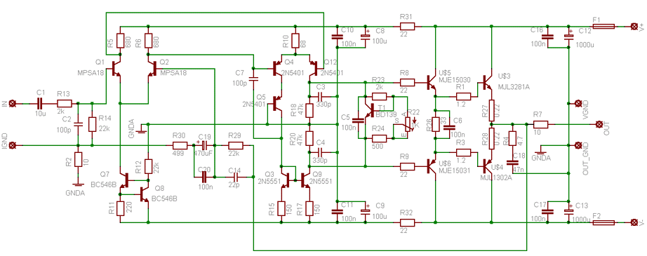
Figure 4: Class AB BJT 100W hi-end-audio

Last Thursday, 26 January 2012 at 3pm, there was a meeting with all FYP students at Gemilang Hall. The agenda is FYP updates and System Engineering. 

Friday, 20 January 2012

WEEK 1

Comparison Study of audio amplifier performances using Class AB, B and D topologies in portable audio devices.


For the first week semester 1, 2012, I had a discussion with my supervisor on planning in this research for this semester. After discussion, I have come out with the Gantt Chart for this semester from week 1 until week 15. Figure show below is my Gantt Chart semester 2 FYP.


Gantt Chart S1'2012

On Tuesday, 17 January 2012 at 3pm, there was a meeting with all FYP students and Engineering Design students at Gemilang Hall. In meeting, the management of FYP want us to create a blog for our own project to replaced the logbook.


Logo of Blogger

So, all the information about the project including photos, videos and softcopy of full report must be upload in this blog. Other than that, all the FYP students degree sem 2 have to buy a t-shirt to be wear on Engineer Day in week 14.